Robots - Notes - Jal and Mark III Servo Code - Timer1 Code
The PARTS Mark III mini-sumo controller board uses the Microchip PIC16F877-20/P. The PIC16F877 is equipped with three hardware timers, Timer0, Timer1, and Timer2. This document describes the use of Timer1 to control two servos. The programming language used in this example is Jal, and the example can be easily ported to other programming languages. The Timer1 can be configured to operate in many different modes but this document will focus on the settings needed to operate it in Timer Mode.
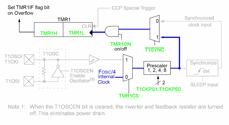
Below is a copy of the "Timer1 Block Diagram" from the "PICmicro Mid-Range MCU Family Reference Guide" pg 12-2. Items in light grey can be ignored because they have no effect when the items in green are set as per the Jal Timer1 setup code listed under the diagram. The blue line indicates the route the Fosc/4 clock takes thru the circuit.

-- timer 1 theory of operation.

-- Timer1 interrupt goes off when the 16 bits of TMR1H:TMR1L role over

-- to zero. This register pair get incremented every prescaler x 4 number of

-- clock ticks. So with a prescaler of 2, the timer registers get

-- incremented every 8 clocks.

--

-- 20ms will take 50000 increments of the TMR1 registers with a 20MHz

-- chip. So on each interrupt we need to initialize TMR1H:TMR1L such

-- that it will roll over in 50000 increments, i.e. 65536 - 50000 = 15536

-- or 0x3cb0. TMR1H = 0x3C, TMR1L=0xB0. Simple.....sort-of.
-- Initialization code. Code execution starts here.


dutycycle_R = 150   -- Set right servo to stop by setting pulse length
to 1.5ms

dutycycle_L = 150   -- Set left servo to stop by setting pulse length
to 1.5ms


-- setup timer 1 and pre-scalar values...

tmr1cs = off        -- Clock Select Bit, 0 =
Use Internal Clock FOSC/4, this sets Timer1


-- into timer mode.

t1ckps1 = off       -- Timer1 Input Clock Prescale
Select bit 1 = 0

t1ckps0 = on        -- Timer1 Input Clock
Prescale Select bit 0 = 1


-- T1CKPS1:T1CKPS0 = 01 = 1:2 Prescale value

t1sync = on         -- Synchronization bit, 1
= do not Synchronize clock input with internal


-- clock. According to lDS31012A 12.3 this bit has no effect if


-- TMR1CS = 0

tmr1on = off        -- Timer1 On bit = 0,
timer is off

f877_tmr1h = 0x3c   -- Set TMR1H to 0x3C or 60. Which will be 256 * 60
= 15360 or 0x3C00

f877_tmr1l = 0xb0   -- Set TMR1L to 0xB0 or 176. TMR1H:TMR1L = 0x3CB0
= 15360 + 176 = 15536


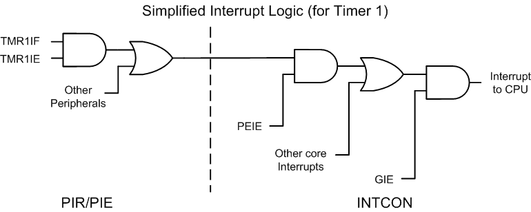
-- setup interrupt logic to detect TMR1 overflow and trigger an interrupt

tmr1if = off        -- Timer1 Overflow
Interrupt Flag bit = 0, ready for overflow. Timer1


-- will set this flag to one when TMR1H:TMR1L overflows from 0xFFFF to


-- 0x0000.

bank_1
-- Switch over to bank 1

tmr1ie = on         -- Timer1 Overflow
Interrupt Enable bit = 1

bank_0
-- Switch back to bank 0

intcon_gie = on     -- Global Interrupt Enable bit = 1

intcon_peie = on    -- Peripheral Interrupt Enable bit = 1


-- start timer 1

tmr1on = on         -- Timer1 On bit =
1, start Timer1

If you have any questions or comments about this page please email me at: debots_replacethis_dinkdaze.org with at sign.