Robots - Notes - Jal and Mark III Servo Code
Jal is a great programming language to use to control the PARTS Mark III Mini-Sumo. It has only a few elements to learn and the syntax is very straight forward. And thanks to Mark Gross, a Mark III version of Jal is very simple to install on a home computer and has many Mark III sample programs. His website provides everything you need to begin using Jal on your Mark III. Once you download it, all you need is a serial cable, your computer, and of course a Mark III.
This document is a deconstruction of the Mark's Jal code that is used to operate the Mark III's servos. It is taken from his popular "sumo.jal" program. It is stripped of most of it's Sumo playing code and is down to just the code that operates the servos. Code is added to make the robot move forward for 6 seconds. To see a full listing of the code see: servocode4.jal
Brief Servo Overview
A hobby servo normally receives a signal that causes it to rotate a specific number of degrees. Typically this rotation is +/- 90 degrees. This is great for operating levers and legs but to turn a wheel you need a servo that has been hacked for continuous rotation. (Search for: Hack Servo Continuous Rotation)
A servo has three wires for power, ground, and a signal. On the signal line, every 20ms, a (hacked) servo receives a pulse of 1.3ms to make it rotate clockwise, or 1.5ms to make it stop, or 1.7 to make it rotate counterclockwise. The right servo is connected to pin B1 and the left servo is connected to pin B2. To move forward the right servo must rotate clockwise and the left servo must rotate counterclockwise.
Program Overview of "servocode.jal"
In operation the program (after the built-in 5 second delay) drives the Mark3 forward for 6 seconds then stops. That's all it does.
The sequence of actions the program takes is as follows:
- Initializes a timer
- Initializes the interrupt logic
- Starts sending pulses to the servos in the background
- Waits 6 seconds
- Stops sending pulses to the servos
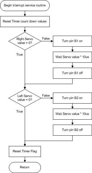
It is very important that the servo pulses occur in the background while leaving the controller program free to do something else, such as send telemetry or check it's position over a line. To make this happen a hardware timer that is built into the PIC16F877 chip is set to go off every 20 ms. When the timer goes off it interrupts the PIC's normal program and calls an "interrupt service routine", or ISR for short. This ISR that occurs every 20ms is responsible for creating the appropriate 1.3ms to 1.7ms pulse on the appropriate B1 or B2 pin. Once these pulses are competed the ISR returns control to the main program.
At start up and prior to running the main program, the code initializes the timer to go off every 20ms. The initialization code also sets the default right and left pulse lengths to 1.5ms so that the servos are stopped until needed. Once the initialization code is complete the main program is executed. This initialization code is the most most complex and will be deconstructed at the very end of this document.
The main program calls the procedure "Forward" then waits 6 seconds. Once 6 seconds is up the program calls the procedure "Stop". The main program spends most of it's time furiously doing nothing as part of the 6 second delay. Many other things could be occurring instead of just a delay.
When ever the timer goes off the main program execution is halted and the ISR is executed.
| ISR Flowchart | Notes | Code |
 |
"pragma interrupt" tells Jal that this is the start of the ISR | procedure timer_isr is |
| This ISR is running therefore TMR1H:TMR1L = 0x0000 and needs to be reset to 0x3CB0 | f877_tmr1h = 0x3c |
|
| This section sends no pulses to the Right Servo if "dutycycle_R" = 0. Other wise it creates the desired pulse by bringing pin B1 high, then delaying "dutycycle_R" * 10us. Then is sets pin B1 low. In most cases "dutycycle_R" is between 130 and 170 giving a pulse of 1.3ms to 1.7ms. | if 0 != dutycycle_R then |
|
| This section sends no pulses to the Left Servo if "dutycycle_L" = 0. Otherwise it creates the desired pulse by bringing pin B2 high, then delaying "dutycycle_L" * 10us. Then is sets pin B1 low. In most cases "dutycycle_L" is between 130 and 170 giving a pulse of 1.3ms to 1.7ms. | if 0 != dutycycle_L then |
|
| Timer1 overflowed setting TMR1IF triggering this ISR. Reset TMR1IF for next interrupt. | tmr1if = off |
|
| Return program step prior to interrupt. | end procedure |
Description of Timer1 Setup/Initialization and Operation.
Links:
PARTS Mark III Mini-Sumo Robot -
http://www.junun.org/MarkIII/ and
http://www.portlandrobotics.org/
Mark Gross -
http://thegnar.org/
Jal - http://www.voti.nl/jal/
and http://jal.sourceforge.net/
If you have any questions or comments about this page please email me at: debots_replacethis_dinkdaze.org with at sign.