![]()
Robots - Notes - One Pin Switch and LED Circuit
 |
This simple circuit is devised to allow
a single microcontroller I/O pin S, for Signal, to operate as an input push
button switch or as an output LED. At 4.9V normal draw is 1.35mA with D1 lit and SW1 open. The table below indicate measurements with pin S in output high, output low, and as input presumably with high z. All measurement were taken with SW1 open (normal) and closed.
Highest draws, 2.2mA, were measured with SW1 closed and pin S
configured as output low. Having the button pushed while the pin is
set to output is not a normal operating condition but the results
seam to be well within the 20mA limit of the pin. |
|||||||||||||||||||||||||||||||||||||||||
|
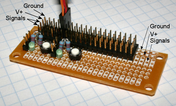
Patch panel with two "One Pin" circuits. Each circuit takes Power, Ground, and MPU pin. |
|
|
If you have any questions or comments about this page please email me at: debots_replacethis_dinkdaze.org with at sign.