![]()
Robots - Notes - Wheel Encoder Bracket
2005-03-28
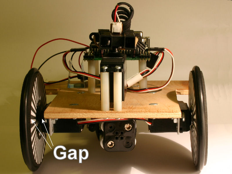
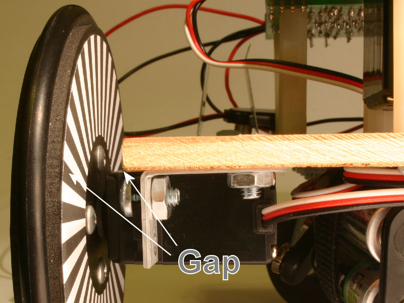
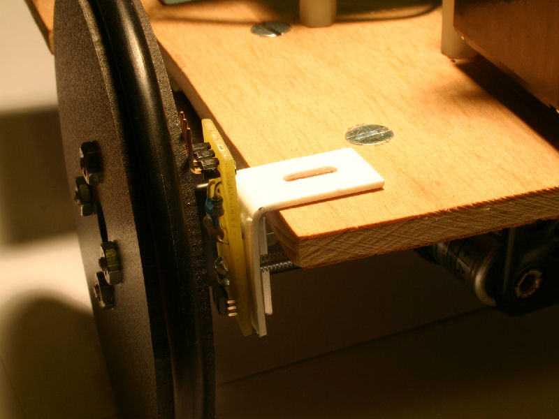
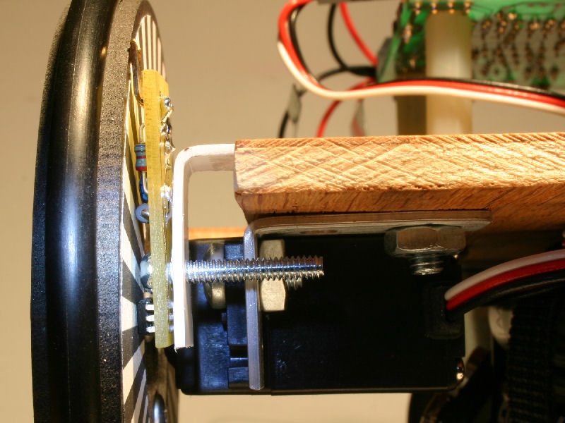
The task was to build a bracket to hold the wheel encoder in place between the robot base and the encoder disk on the wheel, Fig. 1 & Fig. 2. The most important specification is that the encoder sits close to the encoder disk, how close could be the subject of another entry, and be adjustable. It is also a good idea to position the encoder sensor the proper distance between the wheel axle and rim. And finally the encoder should be orientated so that as the wheels spin both the transmitter and receiver are parallel to the encoder sectors and cross over the black to white sectors at the same time.
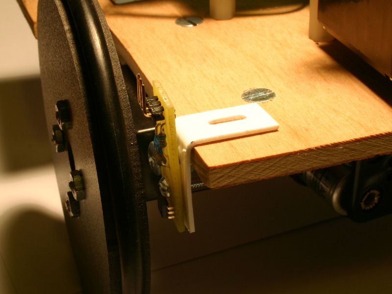
The bracket is made out of a 9/16" strip of .040" (1.0 mm) thick sheet styrene. A slot cut on one end allowed the bracket to be adjustable where it was attached to the robot base. The other end of the bracket had a hole where the encoder could be attached. To bent the strip into a bracket the slotted end of the bracket was clamped between two metal rulers. The straight edge of the ruler would provide the good bend. Heat was applied using the heat gun to the exposed side of the strip but the plastic shrank and deformed to much. The plastic clamped between the rulers did well. For the second attempt the strip was clamped between 4 small flat brass pieces. Double stick scotch tape was used to accurately place the strips and clothes pins were used to clamp the pieces together. Once heat was applied in less than a minute the plastic could be bent into shape.
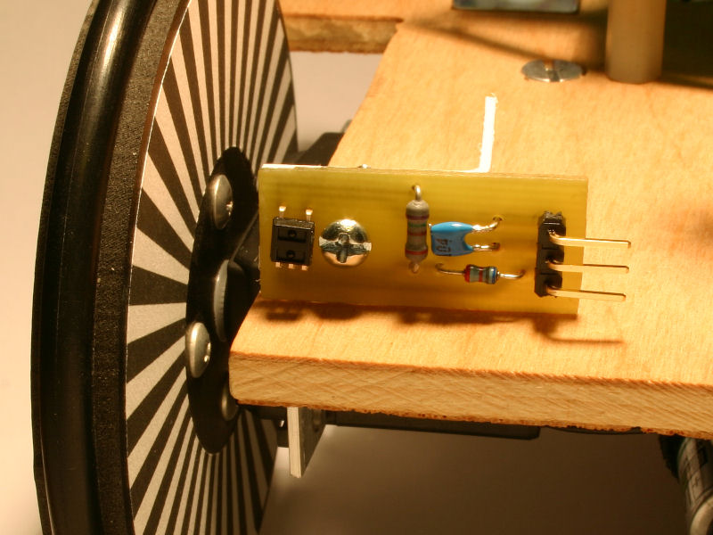
Test fitting the bracket with encoder circuit attached showed that the connector pushed out too close to the wheel, Fig. 7. This would prevent the sensor from being positioned flush or nearly flush with the wheel encoder disk. Which could effect sensor sensitivity. If the homemade circuit board was two sided the connector could have been reversed which would be the ideal position for this robot. However the issue was corrected by removing the black plastic spacer at the base of the .1" connector and re-soldering the connector into this position, Fig. 9.
 |
 |
 |
| Fig. 1 | Fig. 2 | Fig. 3 |
 |
 |
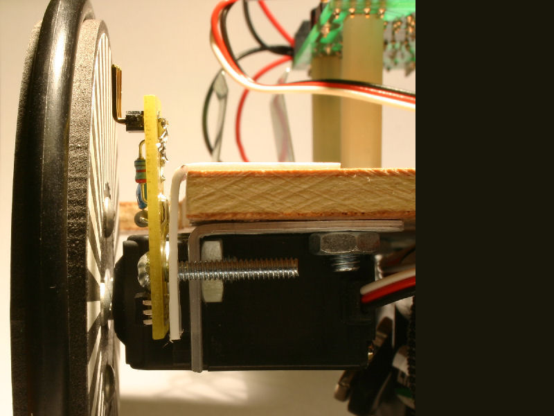
Orthogonal view showing encoder on bracket in wheel gap. Fig. 4, Left with encoder positioned in and Fig. 5, right positioned out. |
| Fig. 4 | Fig. 5 | |
 |
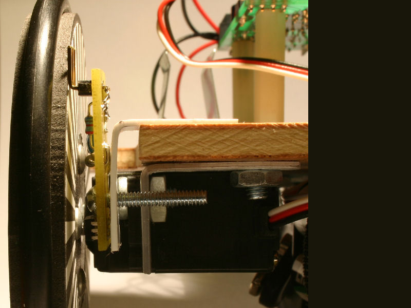 |
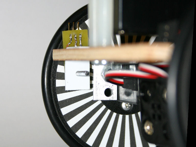
Straight on view showing encoder on bracket in wheel gap. Fig. 6, Left with encoder positioned in and Fig. 7, right positioned out. Notice that original encoder connector would not allow sensor to be positioned flush with the encoder disk. (Not that you'd ever want to do this.) |
| Fig. 6 | Fig.7 | |
 |
 |
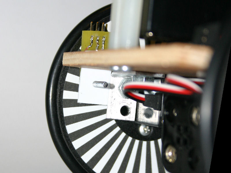
Straight on view showing encoder on bracket in wheel gap. Fig. 8, Left with encoder positioned in and Fig. 9, right positioned out. Notice the modified encoder connector will allow sensor to be positioned flush with the encoder disk. (Not that you'd ever want to do this.) |
| Fig.8 | Fig.9 | |
 |
 |
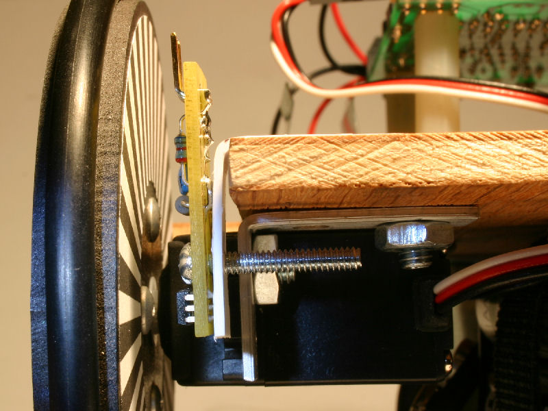
Side view showing encoder on bracket in wheel gap. Fig. 10, Left with encoder positioned in and Fig. 11, right positioned out. You can't see it but the encoder sensor is positioned just below the #4 machine screw. |
| Fig.10 | Fig.11 | |
 |
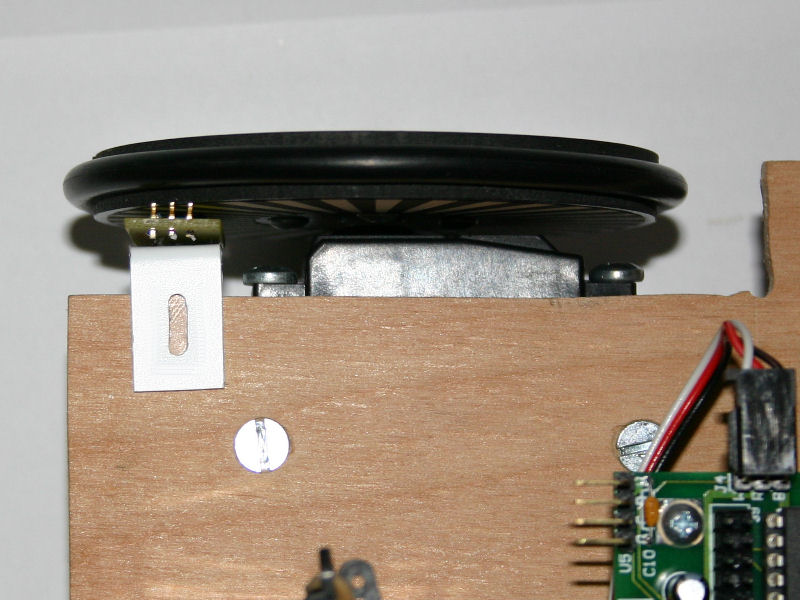 |
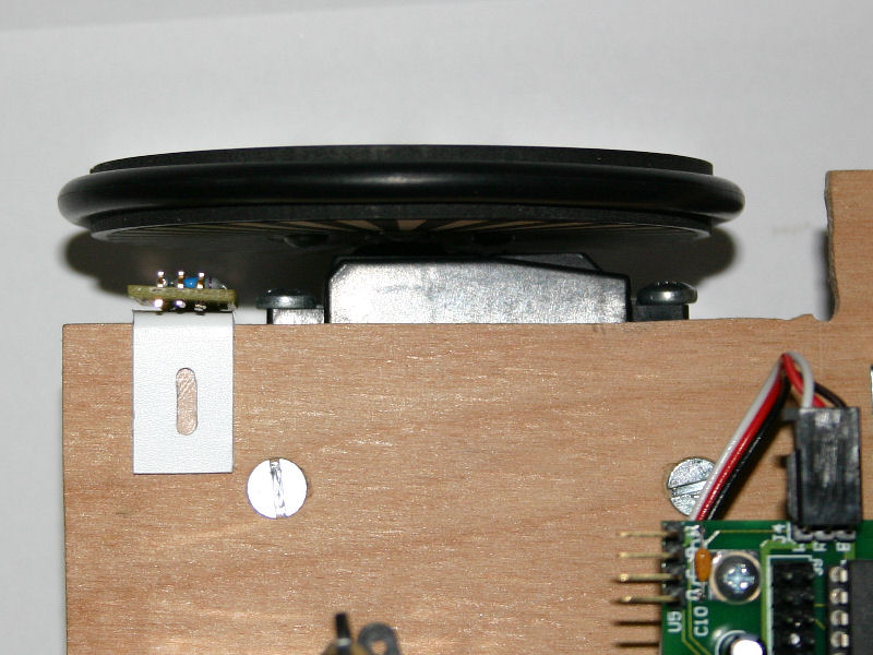
Top view showing encoder on bracket in wheel gap. Fig. 12, Left
with encoder positioned in and Fig. 13, right positioned out. The
slot will allow the bracket to be adjusted in and out. Nylon #4 nuts and screws are on the way. |
| Fig. 12 | Fig. 13 |
If you have any questions or comments about this page please email me at: debots_replacethis_dinkdaze.org with at sign.